A Single Transistor Solid State Tesla Coil
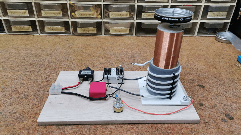
Tesla coils are one of those builds that capture the interest of almost anybody passing by. For the naïve constructor, they look simple enough, but they can be finicky beasts—beasts that can bite if not treated with respect. [Mirko Pavleski] has some experience with them and shares it with us over on Hackaday.io. One of the first big improvements of this build style is the shift from the originally used spark gap commutator to that of a direct AC drive via a MOSFET oscillator. This improves the primary drive power for its size and eliminates that noisy spark gap. That’s one less source of broadband RF noise and the audible racket these produce.
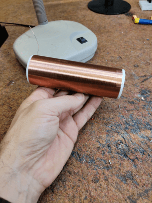
The primary side of a Tesla coil is usually a handful of turns of thick wire to handle the current without melting. This build runs at two or three amps, giving a primary power of around 150 Watts. However, this is quite a small unit; with larger ones, the power is much higher, and the resulting discharge sparks much longer. On the secondary side, the air-coupled coil is formed from 520 turns of much thinner wire since it doesn’t need to convey so much current. That’s the thing with transformers with large turns ratios — the secondary voltage will be much higher, and the current will be correspondingly much lower. The idea with Tesla coils is that the secondary circuit forms a resonant circuit with the ‘top load’, usually some hollow metal can. This forms an LC circuit with a corresponding resonant frequency dependent on the secondary inductance values, the object’s capacitance and anything else connected. The primary circuit is designed to resonate at this same frequency to give maximum power coupling across the air gap. Changing either circuit can spoil this balance unless there is a feedback circuit to keep it in check. This could be with a sense coil, a local antenna or something more direct, like in this case.
To ensure the primary circuit doesn’t melt, it needs to be able to drive a reasonable current at this frequency, often in the low MHz range. This leads to a common difficulty: ensuring the switching transistor and rectifying diode are fast enough at the required current level with enough margin. [Mirko] points out several components that can achieve the operating frequency of around 1.7 MHz, which his top load configuration indicates.
For a bit more info on building these fascinating devices, you could check out our earlier coverage, like this useful guide. Of course, simple can be best. How about a design with just three components?
from Blog – Hackaday https://ift.tt/8hz9gIG


Comments
Post a Comment