Beyond The Basics: Exploring More Exotic Scope Trigger Modes
Last time, we looked at some powerful trigger modes found on many modern scopes, including the Rigol DHO900 series we used as an example. Those triggers were mostly digital or, at least, threshold-based. This time, we’ll look at some more advanced analog triggers as well as a powerful digital trigger that can catch setup and hold violations. You can find the Raspberry Pi code to create the test waveforms online.
In addition to software, you’ll need to add some simple components to generate the analog waveform. In particular, pin 21 of the Pi connects to 2uF capacitor through a 10K resistor. The other side of the capacitor connects to ground. In addition, pin 22 connects directly to the capacitor, bypassing the 10K resistor. This allows us to discharge the capacitor quickly. The exact values are not especially important.
Runt Triggers
A runt pulse is one that doesn’t have the same voltage magnitude as surrounding pulses. Sometimes, this is due to a bus contention, for example. Imagine if you have some square waves that go from 0 to 5V. But, every so often, one pulse doesn’t make it to 5V. Instead, it stops at 3V.
This isn’t easy to catch with a level trigger. After all, if you set the trigger level to 3 V, the normal pulses will trigger the scope, too. That’s where the runt pulse trigger comes in handy.
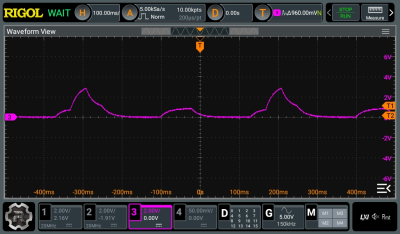
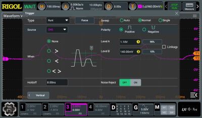
You can, of course, flip the polarity. You can also only trigger on pulses that are longer or shorter than some time limit. However, the key idea is that the pulse has to exceed the lower limit without making it to the upper limit. You can see on the scope trace how the central pulse isn’t as tall as the others. That’s what causes it to trigger.
Slope
Another thing difficult to trigger on is a particular slope. You may have been taught that the slope is the “rise over the run” which is another way of saying the change in Y divided by the change in X. That’s exactly how the scope defines this trigger. For a certain pair of voltages (Y) you can compute the time (X) between those two voltages. If that time is larger or smaller than some preset number, you have a trigger.
You’ll see in the trace below that the center pulse doesn’t gradually decay like the others. Instead, it rapidly discharges to zero. That is a very small slope in that part of the signal. Using the slope trigger, you can find the area easily.
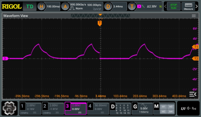
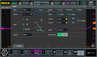
With these settings, the natural slope of the discharge of the capacitor is not enough to trigger the scope. However, the rapid shift does trigger the scope, leaving the trigger on the steep falling edge of the waveform.
Setup and Hold
Our final exotic trigger is one you probably recognize if you’ve worked with flip flops on an FPGA. A flip flop has a data input and a clock input. In theory, of course, all components are perfect, but in the real world, that isn’t the case. So flip flops usually specify a minimum setup and hold time.
What this means is that the data input has to be stable for a certain amount of time before the clock asserts. That’s the setup time. After the clock asserts, the data must not change for short period of time — the hold time. If you violate either of these numbers, the output of the flip flop will be unpredictable.
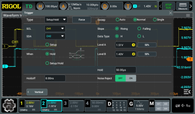
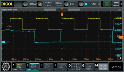
While this seems easy enough to see, there are two things to consider. First, the violation may be much more subtle than it is here. Second, it can be hard to pick out a difference like this out of thousands upon thousands of pulses. With the setup and hold trigger, the scope will immediately point out where you have a problem.
Wrap Up
Do you have to have all these triggering modes? No. People used scopes for decades that did not have these exotic triggering modes. But it sure does make life easier. Some of these events would be very tedious to find manually, even if you could catch them in your scope’s memory.
If you own a different scope brand, you may find subtle differences between the scope we used and yours. Check your scope’s documentation. If you want more details about the modes we’ve talked about, Rigol has many of these modes explained for one of their scopes. You might find those videos useful, too.
Triggering has come a long way in scopes. These posts give you a flavor of the different types of triggering available on modern scopes, but yours may have other features, too. Knowing your scope will help you find problems faster and get a perfect view of just the part of your signal you are interested in.
from Blog – Hackaday https://ift.tt/yBwHJKE
Comments
Post a Comment