Here’s How Those Battery-Free Flashing Phone Stickers Worked
The late 90s and early 2000s were a breakout time for mobile phones, with cheap GSM handsets ushering in the era in which pretty much everybody had a phone. Back then, a popular way to customize one’s phone was to install a sticker that would flash when the phone rang. These required no batteries or any other connection to the phone, and [Big Clive] has dived in to explain how they worked.
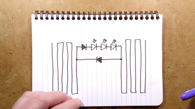
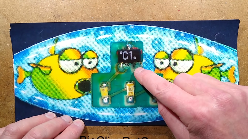
It’s an old-fashioned teardown that requires a bit of cutting to get inside the sticker itself. A typical example had three LEDs in series for a total voltage drop of around 7V, hooked up to two diodes and a PCB trace antenna. A later evolution used raw unpackaged components bonded to the PCB. Future versions went down to a single diode, using the LEDs to serve as the second. The basic theory was that the PCB traces would pick up RF transmitted by the phone when a call was coming in, lighting the LEDs.
In the 2G era, the freuqencies used were on the order of 300 MHz to 1.9GHz. A combination of the change in frequencies used by modern phone technology and the lower transmit powers used by handsets means that the stickers don’t work properly with modern phones according to [Big Clive].
Incidentally, you might like to consider running your own old-school cellphone network. Video after the break.
[Thank to Zane Atkins for the tip!]
from Blog – Hackaday https://ift.tt/mQXMJiu


Comments
Post a Comment