3D Printering: Is Hassle-Free Bed Leveling Finally Here?

3D printers have come a long way over the past several years, but the process of bed leveling remains a pain point. Let’s take a look at the different ways the problem has been tackled, and whether recent developments have succeeded in automating away the hassle.
Bed leveling and first layer calibration tends to trip up novices because getting it right requires experience and judgment calls, and getting it wrong means failed prints. These are things 3D printer operators learn to handle with time and experience, but they are still largely manual processes that are often discussed in ways that sound more like an art than anything else. Little wonder that there have been plenty of attempts to simplify the whole process.
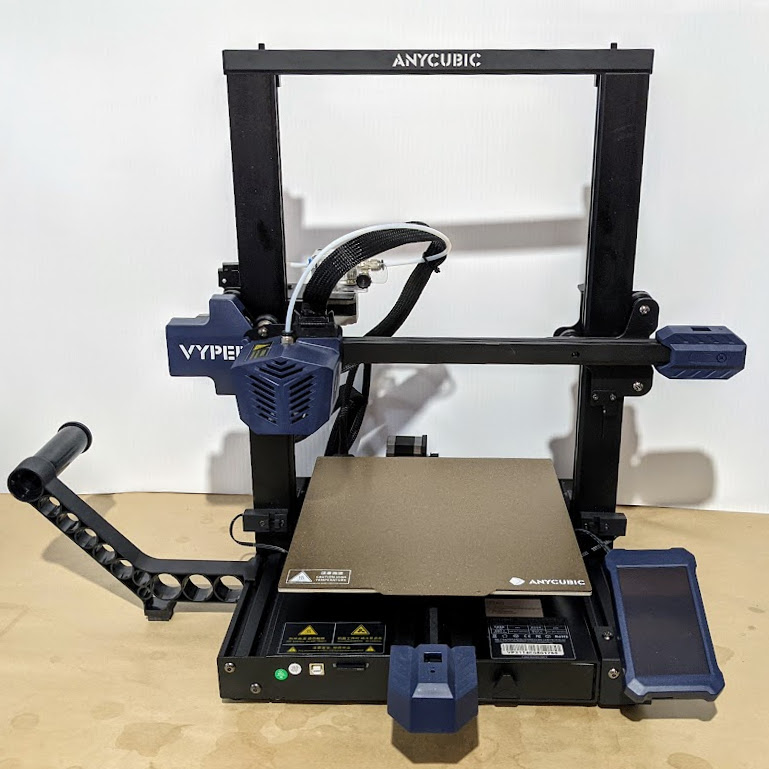
Some consumer 3D printers are taking a new approach to bed leveling and first layer calibration, and one of those printers is the Anycubic Vyper, which offers a one-touch solution for novices and experienced users alike. We accepted Anycubic’s offer of a sample printer specifically to examine this new leveling approach, so let’s take a look at the latest in trying to automate away the sometimes stubborn task of 3D printer bed leveling.
Why is Bed Leveling an Issue?
In 3D printer terms, bed leveling (or simply “leveling”) is a broad term for a process whose end result is getting the first layer of a print deposited optimally onto the build platform. A good first layer is the foundation of a successful print.
To accomplish this, the nozzle needs to remain a constant distance from the build platform across its whole range of movement. If the nozzle is too close to the bed in some places, but too far away in others, that leads to poor quality and failures. Adjusting the printer’s bed until it is parallel to the nozzle’s range of motion is called leveling. (Machinists would correctly call the process tramming, because nothing actually has to be perpendicular to the earth’s gravitational field.)
The next step is first layer calibration. This adjusts the Z-axis offset, or the distance between the tip of the nozzle and the surface of the build platform. There needs to be just enough space for the critical first layer of plastic to be deposited evenly, in a uniform thickness, and pressed into the build surface well enough to remain stuck during printing.
Complicating this is the fact that no build platform is perfectly flat. When fractions of a millimeter count, even small imperfections cause problems. High spots or low spots in a build platform are problems because no amount of tilting the print bed will adjust them away. This is one of the reasons leveling problems have persisted over time.
No individual part of bed leveling is particularly complicated, but the many interconnected factors can make it a complex, fiddly task. It’s no surprise that people have tried different ways to make the whole process as easy and repeatable as possible.
Some Attempted Solutions
Rafts (a type of sacrificial build platform) were an early method of dealing with bed imperfections, but most solutions now revolve around mesh leveling.
Mesh leveling is a method of compensating for an imperfect print bed in software, but it requires a way to measure the build platform. By taking measurements with a sensor, a software model representing the build surface, and its imperfections, can be created. This model modifies the path of the print head as it lays down the critical first layer, adjusting for an imperfect surface by attempting to follow those imperfections, instead of moving as though they don’t exist.
One way to accomplish mesh leveling is by using an inductive sensor to sense the build platform without touching it. Prusa printers use this method to take measurements in a 3 x 3, or optionally 7 x 7, grid before every print. Manually determining an appropriate Z-axis offset for a particular build sheet is still up to the user.
Another option is a physical probe. The BLTouch, for example, is a popular sensor that comes into physical contact with the build platform. Its success as an aftermarket add-on, as well as how often it has been copied, is a good indicator of how much bed leveling remains a pain point for 3D printer owners.
The Latest Approach: Integrating a Strain Gauge
This method uses the tip of the nozzle itself as a sensor. Not only is it easier to take measurements from the point where extrusion actually happens, but doing so opens the door to automatically setting an appropriate Z-offset as well.
One way to do this is by integrating a strain gauge into the extruder itself, turning the hot end into a kind of load cell. We saw this approach in a DIY project that used SMD resistors as strain gauges, and the method is also used in the Smart Effector for delta printers.
Two recent consumer 3D printers, the Anycubic Vyper and the Creality CR-6 SE, implement their own factory-made versions of the idea. We accepted a sample Vyper printer from Anycubic specifically to examine this feature, so let’s take a closer look.
How It Works
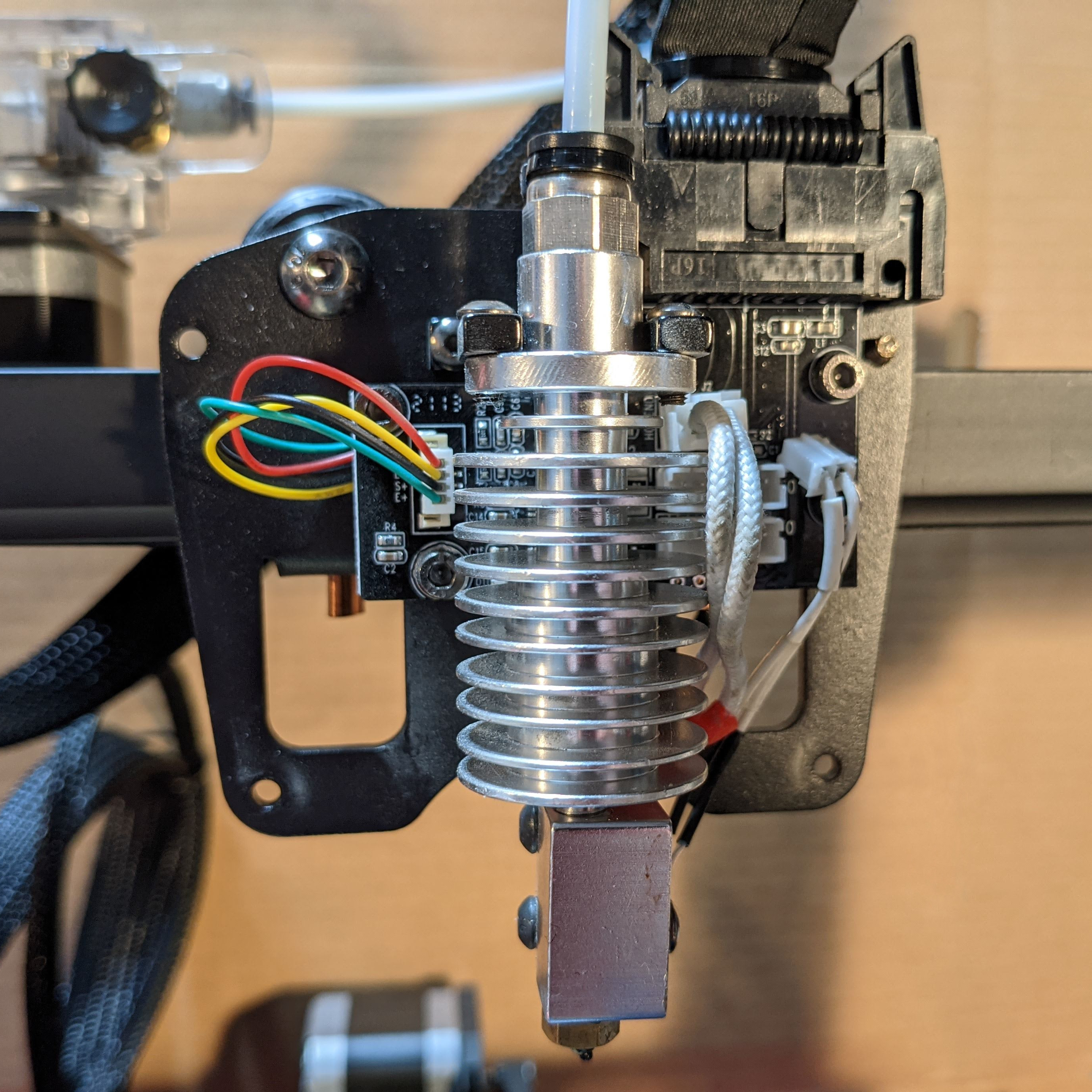
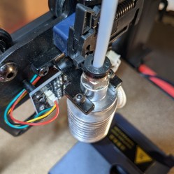
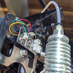
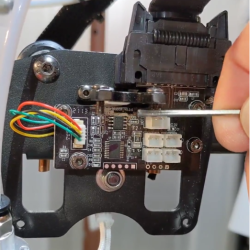
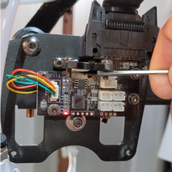
The Anycubic Vyper’s extruder assembly contains a fork-shaped metal mount for the hot end which has a strain gauge built into it. This turns it into a load cell similar to what would be found in an electronic scale.
Any force exerted on the hot end will slightly deform the mount, and the strain gauge turns this deformation into an electrical signal that can be measured and quantified. Even very light pressure on the hot end can be detected in this way.
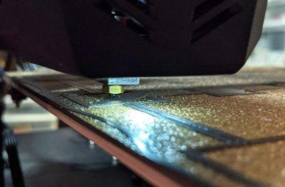
Thanks to this functionality, the nozzle itself becomes a touch sensor. When the machine is directed to auto-level itself, the extruder is repeatedly lowered toward the build platform until the nozzle comes into contact with it. Even a light touch can be reliably detected, so this process doesn’t involve much force.
By taking multiple measurements in a grid pattern, mesh leveling can be implemented. Also, since the physical distance between nozzle tip and build surface can be sensed, a reasonable Z-axis offset can be implemented automatically, leaving the operator to worry only about fine tuning.
It’s a neat idea, and the extruder has clearly been designed around the feature.
Results? Perfectly Serviceable
How well does it work? I’m happy to say the feature appears to work as advertised, including the automatic setting of an effective initial Z-offset.
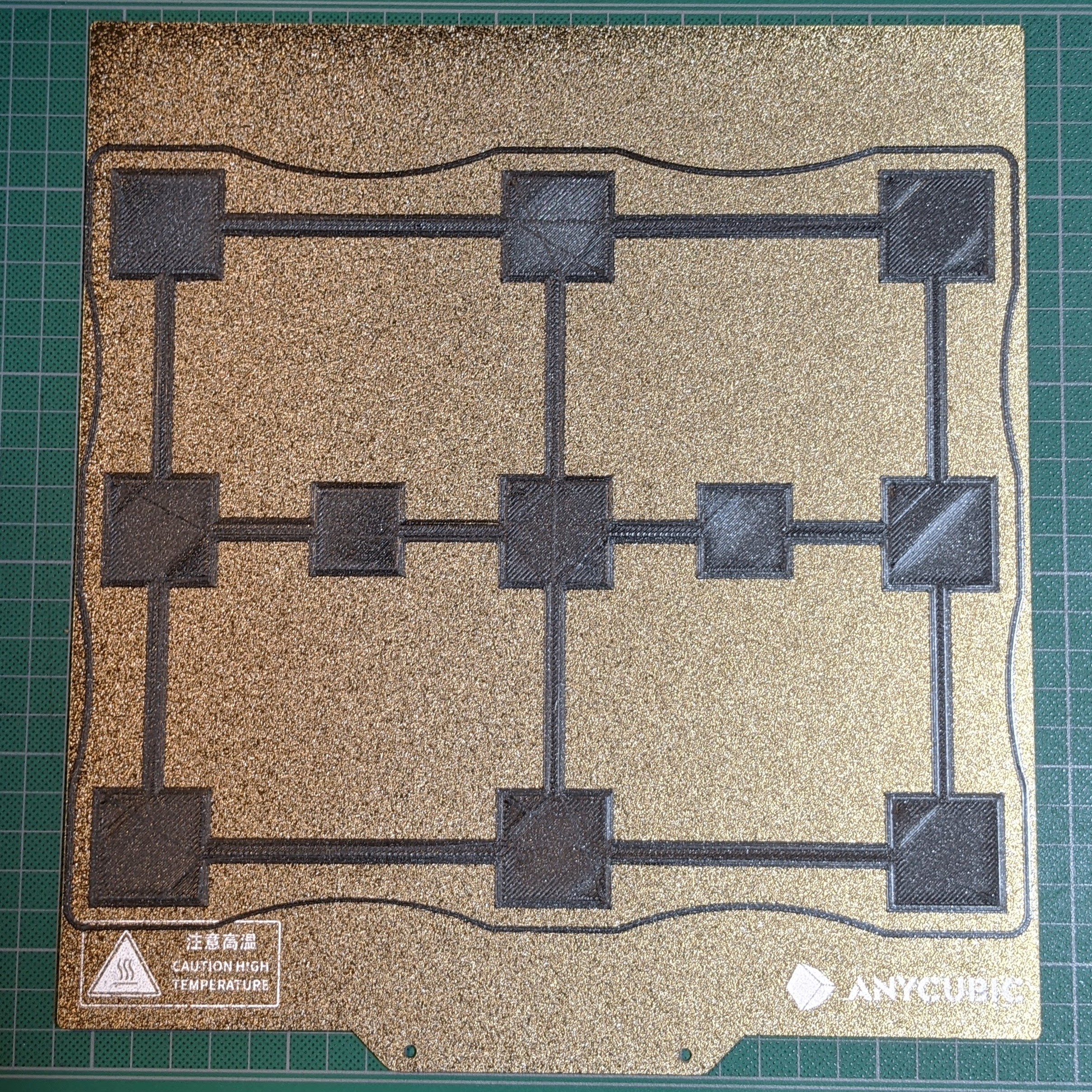
One simply installs the build plate, makes sure the nozzle and the build surface are clean, then instructs the printer to perform the auto-leveling process. The machine will pre-heat, ensuring calibration is done under printing conditions instead of cold, and then the nozzle touches the build platform in a 4 x 4 grid pattern, after which it silently applies mesh leveling and an initial Z-offset that can be fine-tuned if desired. In theory, the process doesn’t need to be repeated unless the build platform changes, but the user can trigger the process whenever they wish.
There Are Limits
The auto-leveling works as advertised, but there are limits to what it can do. First of all, problems related to the quality or type of filament, or the material of the build platform, are separate issues that can still trip up a novice. These are not fixed by an auto-leveling feature.
Both the print surface and the nozzle tip must be clean in order to get the best results, so it’s best to unload filament from the hot end before auto-leveling. Because the machine pre-heats and touches each grid point twice, a loaded nozzle leaves little dabs of molten plastic at each point, and this extra material between the nozzle and the build surface can affect the accuracy of measurements. Indeed, this might be the Achilles heel of all nozzle-based sensors.
There is a limit as to what can be sensed and modeled with a 4 x 4 grid of touch points. A build surface with serious imperfections might not get modeled accurately. I briefly tested this by using shims to simulate mixed high and low spots of up to 0.8 mm in the build sheet before running the auto-leveling process. Unsurprisingly, a 4 x 4 grid of touch points was insufficient to accurately model where exactly these imperfections started and stopped, but I was pleased to see that the resulting first layer was at least still serviceable, if a bit thin and overly-squished around some of the high areas. It would be nice to have an option to increase the number of measurement points, or perhaps manually refine the mesh, as a way to better deal with special cases.
Lastly, the machine’s firmware is not very verbose about the details of its auto-leveling process. There seems to be no way to modify the sensitivity, no way to see the actual measurements taken, and no way to manually fine-tune anything other than the Z-offset, which can be changed up or down in 0.05 mm increments.
Is This The Way?
The Vyper’s auto-leveling and initial Z-offset work as advertised and give serviceable results, even if the firmware is a bit quiet about what exactly is going on under the hood. It’s awfully convenient, the strain gauge integration looks solid, and as a whole it’s a clever system that’s nice to see in a factory offering.
What do you think about this method of automating away the dull drudgery of bed leveling and first-layer tuning? Is turning the hot end into a load cell the right way to go? We want to know what you think, so let us know in the comments.
from Blog – Hackaday https://ift.tt/2WCtHhr


Comments
Post a Comment